
This is the most comprehensive guide to the CAN bus.
In this CAN bus tutorial, you’ll learn about the CAN bus in detail and its applications.
Let’s dive right in:

Contents
What is CAN bus
History of CAN bus
CAN bus Applications
CAN bus layers
CAN bus protocol basics – CAN Messages
Bit Timing
CAN Error Handling
CAN bus Higher Layer Protocols
CAN interface and CAN bus analyzer
Chapter 1:
What is CAN bus
In this chapter we are going to walk you through
Introduction to CAN bus?
Why is is it popular?

CAN bus
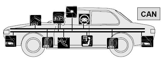
CAN bus (Controller Area Network) is a central networking system that connects different Electronic Control Units (ECU), other devices in a vehicle.
Modern cars can have 100 ECUs So CAN bus communication becomes very important.
Why is CAN bus popular?
- Centralized: CAN bus system allows centralized control over ECUs that are connected to the network so that controlling ECUs becomes easy.
- Robust: CAN bus protocol has a built-in failure detection mechanism so it is robust. When an error is detected, all nodes(ECUs) in the network are informed about this error and all nodes discard this message so that data consistency is guaranteed. CAN bus system is also robust toward electromagnetic interference.
- Low cost and efficient: CAN do not require complex wiring because the communication is not via a direct analog signal. Instead, communicate via a single CAN interface and is a message-based protocol that is very efficient.
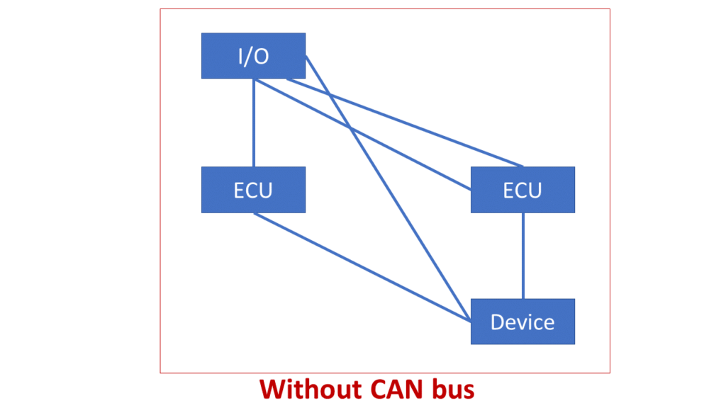
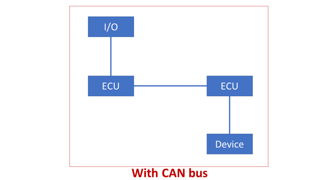
- Flexible: As CAN uses the message-based protocol, the ECUs on the bus do not have IDs associated with them so it is easy to add or remove an ECU.
- Speed: Data transfer speed is important. So depending on the length of the cable, high speed CAN support a data transfer rate between 40 kbps and 1 Mbps.
Chapter 2:
History of CAN bus
In this chapter we will know
Who developed CAN
Time line of its development and application

Robert Bosch GmbH started the development of CAN protocol in 1983 but the CAN protocol was officially released in 1986 at the Society of Automotive Engineers (SAE) conference in Detroit, Michigan.
In 1993, the International Organization for Standardization (ISO) released the CAN standard ISO 11898 which was later restructured into two parts,
- ISO 11898-1 for the data link layer
- ISO 11898-2 for the CAN physical layer for high-speed CAN.
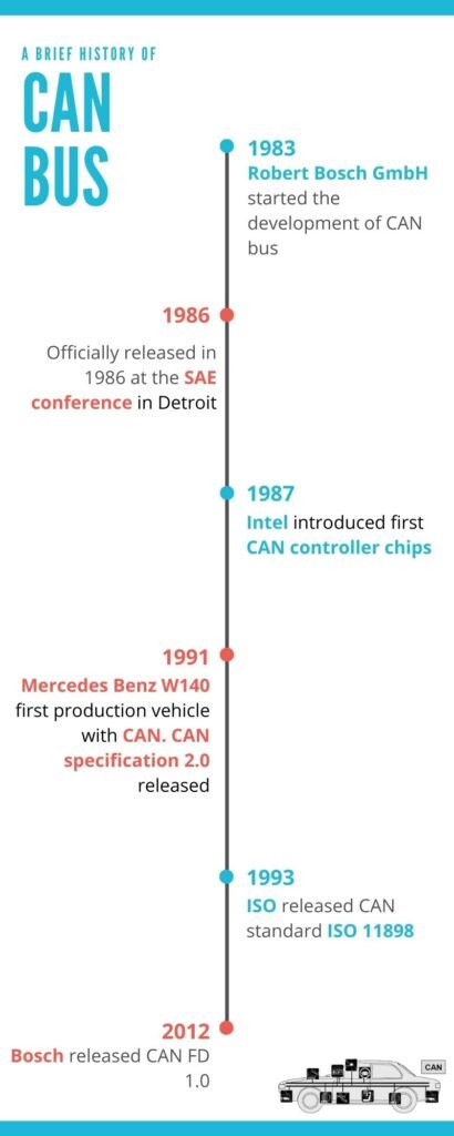
From 1983 a lot of development has happened in CAN as shown above.
Bosch is still working on extending the CAN standards and in 2012, Bosch released CAN FD or CAN with Flexible Data-Rate.
Chapter 3:
Applications of CAN bus
In this chapter we will look into some of the CAN applications especially in Automotive Industry.

The most common application is in-vehicle electronic networking because CAN was created for Automotive use. However over the years CAN has been used in many other applications like in Railways, Industrial automation, Elevators, escalators, etc.
Coming to Automotive,
Because of the focus on safety and comfort in modern automobiles, the most modern automobiles can have 100 Electronic Control Units (ECUs).
The ECUs are mainly used for,
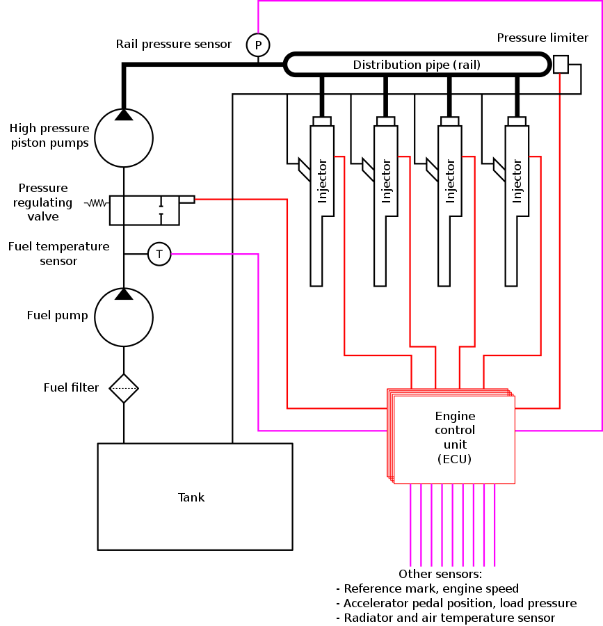
- Engine Control
- Fuel injection systems
- Airbags, transmission
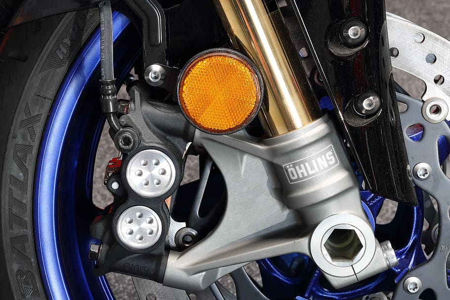
- Antilock Braking System (ABS)
- Electronic power steering, audio systems
- Power windows, doors, and seats
- Battery management systems in electric, hybrid vehicles
and many more areas.
Some of these ECUs interact with sensors and actuators to perform various operations. Below are some examples.
- Fuel Injection: An ECU calculates the throttle pedal angle and sends a signal via the CAN so that other ECUs can use it if needed. The ECU that controls Fuel Injection reads the signal, calculates, and sends a signal to the actuator for the fuel injection. So CAN bus system plays an important role here.
- Antilock Braking System (ABS) ECU interacts with sensors, actuators, and other ECUs via CAN so that effective braking takes place preventing the wheels from locking up during braking.
Chapter 4:
CAN bus layers
In this chapter we will know different CAN layers with focus on
Physical Layer
CAN bus topology

Want to know how CAN protocol works? as a first step let’s understand the CAN layers.
ISO/OSI reference model specifies seven layers below.
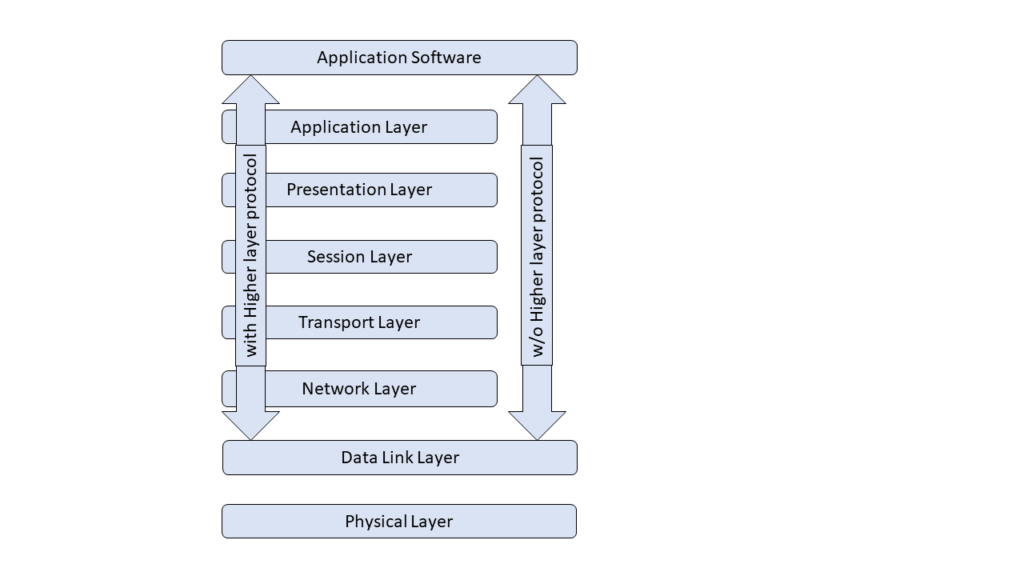
The standard CAN Bus implementation neglects the connection between the Data Link Layer and the Application Layer.
CAN bus Physical Layer
This layer defines the electrical levels, signaling scheme on the CAN bus, the cable impedance, etc. Below are the main types of physical layers:
- The two-wire balanced signaling scheme is defined by the CAN standard, part ISO 11898-2, also knows as high speed CAN.
- Two-wire balanced signaling scheme for lower bus speeds based on ISO standard, ISO 11898-3 also known as low speed CAN.
- Single wire and ground as defined by SAE J2411.
CAN bus topology
Below is a sample CAN network in which nodes are connected with two wires, CAN High (CAN-H) and CAN Low (CAN-L). The CAN bus is terminated by 120 Ohm resistors.
CAN bus termination at both ends of the bus is necessary to remove any electrical reflections on the bus and to guarantee the correct DC levels. Usually, A twisted-pair copper cable with the common ground is used for physical transmission.

Maximum CAN Bus Speed
As per standard, the maximum CAN bus speed is 1 Mbit/s and is achieved via CAN high-speed transceivers.
For low speed CAN, the speed can go up to 125 kbit/s. In standard mode, single-wire CAN go up to 50 kbit/s.
Cable Length
For the arbitration scheme, the wavefront of the signal must go to the most remote node and back again before the bit is sampled, so the maximum length of 40m can be used at CAN speed of 1 Mbit/s.
Chapter 5:
CAN bus protocol basics – CAN Messages
In this chapter we will look into,
CAN messages
Different Frames
Message arbitration

As CAN bus is a broadcast type of bus, all nodes on the CAN bus get all the transmissions. Because of this, we cannot send a specific message to a specific node.
CAN uses short messages. CAN has the below message or frame types.
- Data frame: Contains node data for transmission
- Remote frame: Get the information about the transmission of the corresponding Data Frame
- Error frame: Transmitted when a node detects an error
- Overload frame: Transmitted when a node is overloaded
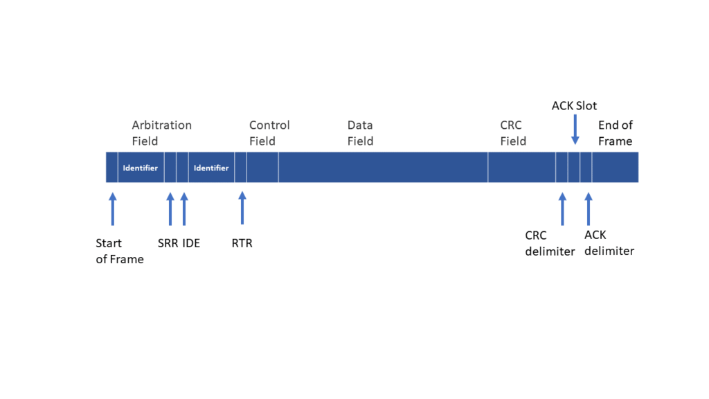
CAN Protocol Frame Format
The Data Frame
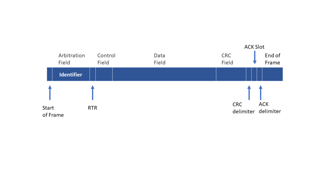
The Data Frame consists of the following parts:
Standard CAN
Extended CAN
Arbitration Field
This determines which message gets the priority when two nodes contending for the bus. It contains,
- 11-bit Identifier and one bit, the remote transmission (RTR) bit dominant for data frames. This is called Standard CAN.
- 29-bit Identifier (includes two recessive bits: Substitute Remote Request (SRR) and identifier extension (IDE) and the RTR bit. This is called Extended CAN.
Data field having 0 to 8 bytes of data
cyclic redundancy check (CRC) field contains a 15-bit checksum for error detection
CRC delimiter
Acknowledgment Slot
ACK delimiter
End-of-frame (EOF)
Remote frame
The remote frame gets information about the transmission of the corresponding Data Frame and it does not have any data field. So, for the request-response type of bus traffic, remote frames are useful.
The Error Frame
Error Frames messages that are not in line with the rules of a CAN message formation. The error frames are transmitted when a node detects an error. The error frame consists of
- ERROR FLAG (6 bits of the same value)
- ERROR DELIMITER (8 recessive bits)
Overload frame
As the name suggests the Overload Frame is transmitted when the node becomes too busy. Usually, the overload frame is not used.
Message arbitration and Priority
Arbitration is the process of deciding which controller will use the bus.
When two or more controllers start transmitting messages at the same time the arbitration becomes important.
If a node sending a recessive level finds the dominant level, then it stops the arbitration and becomes a receiver. This process makes sure that there is no delay to the higher-priority message, and the node that is sending the lower priority message will itself attempts to re-transmit six bit clocks after the end of the dominant message.
Chapter 6:
Bit Timing
In this chapter we will
run through CAN bus Bit
Timing including Clock
Synchronization

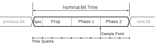
Each bit on the CAN is divided into at least 4 quanta. The quanta are divided into the below types.
- The Synchronization Segment – Used for clocks synchronization and is one quantum long
- The Propagation Segment – Compensate for the delay in the Bus
- Phase Segment 1 – shortened to keep the clocks in sync
- Phase Segment 2 – lengthened to keep the clocks in sync
Clock Synchronization
CAN controller may shorten or lengthen a bit by certain quanta so as to adjust the on-chip bus clock. This is called Synchronization Jump Width (SJW)
Chapter 7:
CAN Error Handling
In this chapter we go
through the inbuilt error
handling mechanism of
CAN
CAN protocol has an inbuilt error handling mechanism that detects errors in CAN messages so that the error detected as soon as possible.
The node transmits an error flag as soon as it detects the error. Other nodes discard the current message as soon as they detect an error flag.
Each node has two error counters,
- Transmit Error Counter (TEC)
- Receive Error Counter (REC)
With the help of these error counters a CAN node detects faults and confines the error.
Below are the Error Detection methods mentioned in the CAN protocol.
- Bit Monitoring
- Bit Stuffing
- Frame Check
- Acknowledgment Check
- Cyclic Redundancy Check
Bit Monitoring
Bit Monitoring ensures the integrity of transmitted data. Each transmitter on the CAN bus reads back the transmitted data and if there is a difference in the transmitted data and the actual data that is read, the bit error raised.
Bit Stuffing
Bit Stuffing is a process in which a node inserts a bit of the opposite polarity after it receives the five consecutive bit of the same polarity.
The receivers remove the extra bit that was inserted. Stuff Error is raised when more than five consecutive bits of the polarity occurs on the CAN bus.
Frame Check
Some parts have a fixed format in a CAN message. If a node detects an invalid value in CRC Delimiter, ACK Delimiter, End of Frame, Intermission then a Form Error Signal is raised.
Acknowledgment Check
Nodes are expected to send a dominant bit in the Acknowledgement Slot in the message when it receives a message. If the dominant bit is missing in the ACK slot, then an Acknowledgement Error is raised.
Cyclic Redundancy Check Cyclic Redundancy Checksum (CRC) is raised when a node detects a different CRC in the message than what it has calculated itself.
Chapter 8:
CAN bus Higher Layer Protocols
In this chapter we will
give a brief summary of
CAN Higher Layer
protocols

CAN standard defines the Physical Layer (Hardware) and the data link layer (basic communication layer).
A Higher Layer Protocol is required to manage communication in a system.
There are many Higher Layer Protocols, some of the most commonly used are,
- CANopen
- J1939
- CAN Communication Protocol (CCP)
- MilCAN
- CanKingdom
- ARINC
Chapter 9:
CAN interface and CAN analyzer
In this chapter we will
give brief details about
getting the CAN data and
Analysis.

Wondering how to read can bus data?
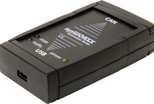
Reading CAN bus requires looking at the hardware signals. CAN interface and CAN analyzer is required.
CAN interface is hardware to connect a CAN bus to the laptop or PC for analysis. It will have a CAN transceiver.
For CAN analysis CAN analyzer software is required which collects the CAN data through the CAN interface.
Conclusion

In this guide, we looked at everything there is to know about the CAN bus. From what is CAN bus to its History to CAN application and more.
Now it’s your turn: Please let me know if you need any further information on the CAN bus?
Leave a comment below to let me know.


All very helpful information that I will be using for my job every day.
Нi there to every one, it’s in fact a fastidious for me to
paү а vіsit this site, it contains helpful Information.